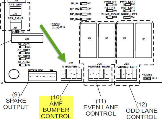

You will have to now pass the belt through the return track assembly by removing nuts index 12 page 189 and cap screw index 39 page 189 from track index 1 page for the even numbered pinsetter and remove index 12 page 189 and cap screw from the track index 2 page 189 for the odd machine, you will also have to remove the index 3 page 189 from the ball joint index 36 page 189.ġ9. Remove nuts index CC 14 from J bolts CC 15 page 89.ġ7. Remove turn pan spring index CC 4 that holds turn pan to the cross conveyor frame.ġ6. The belt should now just be hanging over the top of the turn pan and cross conveyor.ġ5. Take the ball wheel belt and pass around the pinsetter motor towards the front of the pinsetter and send it between the motor mount index E 116 and frame of the pinsetter.ġ4. Unplug pinsetter motor and remove hex head screw index E 83 and nut index E 99 from the motor mount index E 116 on page 147. Push ball wheel belt up between bracket index E 18 K and elevator frame, move belt up and over the sheave index E 39 on page 143 and let it lay over the cross conveyor assembly.ġ3. Lift the ball wheel index E 142 page 145 and remove ball wheel belt from the under side of the ball wheel and just let it lay on pit carpet.ġ2. Loosen the screws just enough to raise the arms up off the ball wheel.ġ1. Loosen ball wheel guide rollers on the left and right side of the ball wheel by loosening nuts on the guide roller arms index E 130 and index E 134 on page 145. Remove left hand wheel guard by Index E 57 page 143 by removing both mounting screws index E 150 and index 117 A page 143 and remove guard.ġ0.

#Brunswick gsx pinsetter manual parts Pc
Remove pit conveyor idler assembly by removing screw index PC 6 page 79.ĩ. Remove hex head screws index E 18 A from inside bracket index E 18 K on page 141.Ĩ. Remove idler assembly index E 31 page 143 by removing both hex head screws index E 80 page 143 from the shaft index E 32 on page 143 and remove ball wheel belt idler.ħ. Remove idler tension for ball wheel belt by pushing up on the idler assembly index E 31 page 143 and remove ball wheel belt from under the pulley.Ħ. Remove tension spring E 8 page 141 and long turret belt index E 3 page 139 and cross conveyor drive belt E 4 page 139.ĥ.

Remove Belts from the pinsetter motor to gear box belts and motor to elevator belts.Ĥ. Remove back Elevator Guard index E 45 page 143.ģ. Disconnect power cord and turn off circuit breaker on the electrical box.Ģ. A-2 Low Voltage Electrical Trouble Shooting Schematicġ. board, expect lights at LEDs:ĭ12 indicates when the right sweep is down.ĭ14 indicates when the left sweep is down.ġ.4.3.1.2. The below image is an example of a V6.0 Distribution board: board, expect lights at LEDs:ĭ20 indicates when the right sweep is down.ĭ26 indicates when the left sweep is down.

Manually drop either rake to confirm if the correct LED lights up for the lane that you dropped the sweep on.The Sweep Switch wiring is incorrect or reversed at the distribution board connections J1 Left and J2 Right.Ī. Ensure that the correct sweep switch cable from the pinsetter representing the odd and even lane is plugged into the proper odd/even lane ports J1 and J2 of the Distribution board. Left pinsetter drops sweep and right lane cycles continuously after first ball.Second lane drops the sweep and scores, and both cycle continuously. Lane Pair: One lane sweep drops and no scoring or triggering.Single Lane: Either Lane assignment: Sweep drops and machine will not score on automatic trigger.


 0 kommentar(er)
